


 Abstract
 HTML
HTML Reference
 Related
 PDF
PDF


-
Dark matter (DM) poses major problems in modern astronomy and physics. Although there is indirect evidence of its existence, such as cosmic microwave background radiation (CMB), rotation curves (RC) of spiral galaxies, mass-to-light ratios of elliptical galaxies, measurements of large-scale structures of the universe, and so on, physicists and astronomers have so far been unable to directly detect DM particles or even theoretically determine what constitutes them [1, 2]. The problem of DM still faces great challenges and opportunities. For example, the cold dark matter (CDM) model that has attracted the most attention from researchers has small-scale observation problems, which mainly include the missing satellites problem (MSP) [3-5], the cusp-core problem (CCP) [6-9], the rotation curve diversity problem (RCD) [10, 11], etc. In recent years, using the measurement of gravitational waves (GWs) [12-17] and black hole shadows (BHSs) [18-21], scientists have been able to study the properties of DM near black holes (BHs); this has opened up a new approach for DM detection.
Therefore, it is particularly important to understand the effect of a BH on the distribution of DM. We know that there is an innermost stable circular orbit (ISCO) near an intermediate mass black hole (IMBH) [13, 14]. When the DM particles are within the radius of the ISCO, the DM will not be able to form a stable distribution. The existence of a BH makes the DM distribution around the BH appear as a density cusp, which is the famous DM spike phenomenon [22, 23]. Using an adiabatic approximation and Newton's approximation, Gondolo and Silk [22] studied the DM distribution under the Schwarzchild BH and found that the distribution form was
$\rho_{\rm{DM}}(r) = $ $ \rho_{\rm{sp}}(1-8GM/c^{2}r)^{3}(r_{\rm{sp}}/r)^{\alpha}$ . Meanwhile, they also proposed that the DM distribution around the BH can be replaced by the power-law profile, and the results show that the DM density is zero at$ 8GM/c^{2} $ (i.e.,$ 4R_{s} $ , the Schwarzchild radius$ R_{s} = 2GM/c^{2} $ ). In the case of adiabatic approximation, Sadeghian et al. [24] obtained different results from [22] using rigorous general relativity (GR). They found that the DM density was zero at$ 4GM/c^{2} $ (i.e.,$ 2R_{s} $ ) and increased by more than 15 percent at the peak of the spike, which may cause observable effects in GW events of the intermediate-mass-ratio inspiral (IMRI) system.The existence of BHs can greatly increase the density of DM. If DM annihilates into gamma-ray photons, it will enhance the possibility of detecting DM signals. In contrast, the DM near a BH may have significant dynamical effects, including two aspects. One is the effect of DM on the stellar orbital dynamic. It has been found that the effect is very small, and that there is no observable effect. The other is the effect of DM on GW signals generated during a compact binary merger. Eda et al. [13] found that the DM spike around the center IMBH has a significant impact on the GW signals of the IMRI system, which indicates that the observation of the GW from the IMRI may be of great help in the exploration of DM models. Recently, Yue and Cao [12] studied the enhancement of eccentricity and GW signals for IMRIs by DM spikes, but they did not study the changes of eccentricity due to the differences of the center IMBH masses and DM models. In addition, they assumed that the DM spike satisfies a power law profile. In fact, the DM spike could meet a more rigorous distribution. In this work, we will focus on these two issues.
The outline of this paper is as follows. In Section II, we present the DM distribution with spikes and without spikes. In Section III, we study the enhancement effect of eccentricity for an IMRI with different center IMBH masses and DM distributions. The summary and conclusions are given in Section IV.
-
(1) DM profile with spike
According to reference [22], when Newton's approximation and adiabatic approximation are considered, the distribution of DM spikes is
$ \rho_{\rm{DM}}(r) = \rho_{\rm{sp}}(1-8GM/c^{2}r)^{3} $ $ (r/r_{\rm{sp}})^{-\alpha} $ . When considering GR and adiabatic approximation, Sadeghian et al. [24] obtained the distribution of DM spikes as$ \rho_{\rm{DM}}(r) = \rho_{\rm{sp}}(1-4GM/c^{2}r)^{3}(r/r_{\rm{sp}})^{-\alpha} $ . Comprehensively considering the influence of relativity, we proposed a more general distribution of DM spikes, which is expressed as$ \rho_{\rm{DM}}(r) = \rho_{\rm{sp}}\left(1-\dfrac{kGM}{c^{2}r}\right)^{3}\left(\dfrac{r_{\rm{sp}}}{r}\right)^{\alpha} , $

(1) where
$ r_{\rm{sp}} $ is the radius of a DM spike,$ \rho_{\rm{sp}} $ is the DM density at the radius$ r_{\rm{sp}} $ , M is the mass of the IMBH, and k is a constant such that$ 4\leqslant k\leqslant 8 $ (k is equal to$ 4 $ in the GR case, and k is equal to$ 8 $ in the Newton approximation case) [22, 24-26]. In this work, the results are the same whether k is$ 4 $ or$ 8 $ , so we take$ k = 4 $ . G is the gravitational constant, c is the speed of light, and$ \alpha $ is the power law index of the DM spike (in this paper, we assume$ 1.5\leqslant \alpha\leqslant 7/3 $ [27-29]). According to the reference [12, 14], we set$ r_{\rm{sp}} = 0.54 \rm{pc} $ and$ \rho_{\rm{sp}} = 226M_{\odot}/ \rm{pc}^{3} $ .(2) DM halo without spike
(i) Navarro-Frenk-White (NFW) density profile
Based on the cosmological constant plus cold dark matter (
$ \Lambda $ CDM) model and numerical simulation [27, 30, 31], an approximate analytical expression of the NFW density profile is derived and is expressed as$ \rho_{\rm{NFW}}(r) = \dfrac{\rho_{\rm{0}}}{\dfrac{r}{R_{\rm{s}}}\left(1+\dfrac{r}{R_{\rm{s}}}\right)^{2}}, $

(2) where
$ \rho_{0} $ is the DM density when the DM halo collapses, and$R_{\rm s}$ is the scale radius.(ii) Thomas-Fermi (TF) density profile
Based on the Bose-Einstein condensation dark matter (BEC-DM) model and TF approximation [32], the DM density profile is given by
$ \rho_{\rm{TF}}(r) = \rho_{\rm{0}}\dfrac{\sin(kr)}{kr}, $

(3) where
$ \rho_{0} $ is the center density of the BEC-DM halo;$ k = \pi/R $ , where R is the radius when the DM pressure and density vanish.(iii) Pseudo-isothermal (PI) density profile
Based on the modified Newtonian dynamics (MOND) model [33], the DM density profile is given by
$ \rho_{\rm{PI}}(r) = \dfrac{\rho_{\rm{0}}}{1+\left(\dfrac{r}{R_{\rm{c}}}\right)^{2}}, $

(4) where
$ \rho_{0} $ is the center density of DM, and$R_{\rm c}$ is the scale radius.In this work, we set
$ R_{\rm{s}} $ , R, and$ R_{\rm{c}} $ as$ 0.54 \rm{pc} $ , and$ \rho_{0} = 226M_{\odot}/ \rm{pc}^{3} $ [12, 14]. -
For a binary system that includes a small compact object and an IMBH, if the mass of the small compact object is much lesser than the mass of the IMBH, this binary system can be reduced to the small compact object moving in the gravitational field of the center IMBH. Next, we use the same method as in [12] to derive the dynamical equations. According to Newtonian mechanics, the small compact object moves on the IMBH's equatorial plane, and the angular momentum is
$ L = \mu r^{2}\dot{\phi} , $

(5) where
$ \mu $ is the mass of the small compact object, r is the distance of the binary system, and$ \phi $ is the angular position of the small compact object. Based on equation (5), the total energy is written as$ E = \dfrac{1}{2}\mu\dot{r}^{2}+\dfrac{1}{2}\mu r^{2}\dot{\phi}^{2}-\dfrac{GM\mu}{r} = \dfrac{1}{2}\mu\dot{r}^{2}+\dfrac{L^{2}}{2\mu r^{2}}-\dfrac{GM\mu}{r} . $

(6) Here without considering the dissipation, the energy E and the angular momentum L are conserved. The semi-latus rectum p and the eccentricity e can be described by E and L [34], and the results are
$ p = \dfrac{L^{2}}{GM\mu^{2}} $

(7) and
$ e^{2} = 1+\dfrac{2EL^{2}}{G^{2}M^{2}\mu^{3}} . $

(8) We now consider the effects of GW emission and dynamical friction in the binary system, where E and L are no longer conserved. Differentiating equations (7) and (8), we obtain
$ \dot{p} = \dfrac{2L}{GM\mu^{2}}\dot{L} = \dfrac{2}{\mu}\sqrt{\dfrac{p}{GM}}\dot{L} $

(9) and
$ \dot{e} = \dfrac{p}{GM\mu e}\dot{E}-\dfrac{(1-e^{2})}{e\mu\sqrt{GMp}}\dot{L} . $

(10) In the case of adiabatic approximation, we consider
$ \dot{E} $ and$ \dot{L} $ as the time-averaged rates, and they are$ \dot{E} = \langle\dfrac{{\rm d}E}{{\rm d}t}\rangle_{\rm{GW}}+\langle\dfrac{{\rm d}E}{{\rm d}t}\rangle_{\rm{DF}} , $

(11) $ \dot{L} = \langle\dfrac{{\rm d}L}{{\rm d}t}\rangle_{\rm{GW}}+\langle\dfrac{{\rm d}L}{{\rm d}t}\rangle_{\rm{DF}} , $

(12) where the symbol
$ \langle\rangle $ represents the time average, the subscript GW represents the loss of the energy caused by GW emission, and the subscript DF represents the loss of angular momentum caused by dynamical friction.Based on the minimum order of post-Newtonian approximation [34-36], the loss of energy and angular momentum due to GW can be expressed as
$ \langle\dfrac{{\rm d}E}{{\rm d}t}\rangle_{\rm{GW}} = -\frac{32}{5}\dfrac{G^{4}\mu^{2}M^{3}}{c^{5}p^{5}}(1-e^{2})^{\frac{3}{2}}\left(1+\dfrac{73}{24}e^{2}+\dfrac{37}{96}e^{4}\right) , $

(13) $ \langle\dfrac{{\rm d}L}{{\rm d}t}\rangle_{\rm{GW}} = -\dfrac{32}{5}\dfrac{G^{\frac{7}{2}}\mu^{2}M^{\frac{5}{2}}}{c^{5}p^{\frac{7}{2}}}(1-e^{2})^{\frac{3}{2}}\left(1+\dfrac{7}{8}e^{2}\right) . $

(14) When the stellar massive compact object passes through the DM halo around the IMBH, it gravitationally interacts with the DM particles; this effect is called dynamical friction or gravitational drag [37]. The dynamical friction force is given by [14, 37]
$ F_{\rm{DF}} = \dfrac{4\pi G^{2}\mu^{2}\rho_{\rm{DM}}(r)\ln\Lambda}{\upsilon^{2}} . $

(15) Here, we set the Coulomb logarithm
$ {\rm ln}\Lambda\simeq 10 $ [38]. The radius r satisfies$ r = p/(1+e\cos\phi) $ . The total energy E is the sum of the gravitational potential and the kinetic energy of the stellar massive compact object, i.e.,$ E = -GM\mu/r+\mu \upsilon^{2}/2 $ . Then, combining equations (7) and (8), we obtain the velocity$ \upsilon $ of the small compact object$ \upsilon = \sqrt{\dfrac{2E}{\mu}+\dfrac{2GM}{r}} = \left(\dfrac{GM}{p}\right)^{\frac{1}{2}}\sqrt{(e^{2}-1)+2(1+e\cos\phi)} . $

(16) According to equations (1), (15), and (16), we can obtain the average energy loss rate caused by dynamical friction:
$ \begin{aligned}[b] \langle\frac{{\rm d}E}{{\rm d}t}\rangle_{\rm{DF}}=&\dfrac{1}{T}\int_{0}^{T}\dfrac{{\rm d}E}{{\rm d}t}\mid_{\rm{DF}}{\rm d}t=\dfrac{1}{T}\int_{0}^{T}F_{\rm{DF}} \upsilon {\rm d}t=\dfrac{1}{T}\int_{0}^{T}\dfrac{4\pi G^{2}\mu^{2}\rho_{\rm{DM}}(r)\ln\Lambda}{\upsilon} {\rm d}t \\ =&\dfrac{1}{T}\int_{0}^{T}\dfrac{4\pi G^{\frac{3}{2}}\mu^{2}\rho_{\rm{sp}}r_{\rm{sp}}^{\alpha}\ln\Lambda (1+e\cos\phi)^{\alpha}\left(p-\dfrac{kGM}{c^{2}}(1+e\cos\phi)\right)^{3}}{p^{\alpha+\frac{5}{2}}M^{\frac{1}{2}}(1+2e\cos\phi+e^{2})^{\frac{1}{2}}} {\rm d}t \\ =&(1-e^{2})^{\frac{3}{2}}\int_{0}^{2\pi}\dfrac{2G^{\frac{3}{2}}\mu^{2}\rho_{\rm{sp}}r_{\rm{sp}}^{\alpha}\ln\Lambda (1+e\cos\phi)^{\alpha-2}\left(p-\dfrac{kGM}{c^{2}}(1+e\cos\phi)\right)^{3}}{p^{\alpha+\frac{5}{2}}M^{\frac{1}{2}}(1+2e\cos\phi+e^{2})^{\frac{1}{2}}} {\rm d}\phi . \end{aligned} $

(17) Based on the geometrical relation, the angular momentum loss rate resulting from dynamical friction can be expressed as
$({\rm d}L/{\rm d}t)_{\rm{DF}} = r\cdot F_{\rm{DF}}(r\dot{\phi}/\upsilon)$ . Substituting equations (1), (5), (7), (15), and (16) and taking r the same as before, we obtain the average loss rate of angular momentum:$ \begin{aligned}[b] \langle\frac{{\rm d}L}{{\rm d}t}\rangle_{\rm{DF}}=&\dfrac{1}{T}\int_{0}^{T}\dfrac{{\rm d}L}{{\rm d}t}\mid_{\rm{DF}}{\rm d}t=\dfrac{1}{T}\int_{0}^{T}\dfrac{4\pi G\mu^{2}\rho_{\rm{DM}}(r)p^{2}\ln\Lambda}{M(1+2e\cos\phi+e^{2})^{\frac{3}{2}}}{\rm d}t \\ =&\dfrac{1}{T}\int_{0}^{T}\dfrac{4\pi G\mu^{2}\rho_{\rm{sp}}r_{\rm{sp}}^{\alpha}\ln\Lambda(1+e\cos\phi)^{\alpha}\left(p-\dfrac{kGM}{c^{2}}(1+e\cos\phi)\right)^{3}}{p^{\alpha+1}M(1+2e\cos\phi+e^{2})^{\frac{3}{2}}}{\rm d}t \\ =&(1-e^{2})^{\frac{3}{2}}\int_{0}^{2\pi}\dfrac{2G\mu^{2}\rho_{\rm{sp}}r_{\rm{sp}}^{\alpha}\ln\Lambda(1+e\cos\phi)^{\alpha-2}\left(p-\dfrac{kGM}{c^{2}}(1+e\cos\phi)\right)^{3}}{p^{\alpha+1}M(1+2e\cos\phi+e^{2})^{\frac{3}{2}}}{\rm d}\phi . \end{aligned} $

(18) In equations (17) and (18), we have used a relation in the last step, i.e.,
$\displaystyle\int_{0}^{T}(...)\dfrac{{\rm d}t}{T} = (1-e^{2})^{\frac{3}{2}}\displaystyle\int_{0}^{2\pi}(1+ e\cos\phi)^{-2} (...)\dfrac{{\rm d}\phi}{2\pi}$ . Substituting equations (13), (14), (17) and (18) into (11) and (12), we obtain the total loss rate of energy and angular momentum resulting from GW and DF:$ \dot{E} = -\dfrac{32}{5}\dfrac{G^{4}\mu^{2}M^{3}}{c^{5}p^{5}}(1-e^{2})^{\frac{3}{2}}\left(1+\dfrac{73}{24}e^{2}+\dfrac{37}{96}e^{4}\right)-\dfrac{2G^{\frac{3}{2}}\mu^{2}\rho_{\rm{sp}}r_{\rm{sp}}^{\alpha}\ln\Lambda}{p^{\alpha+\frac{5}{2}}M^{\frac{1}{2}}}(1-e^{2})^{\frac{3}{2}}\int_{0}^{2\pi}\dfrac{(1+e\cos\phi)^{\alpha-2}\left(p-\dfrac{kGM}{c^{2}}(1+e\cos\phi)\right)^{3}}{(1+2e\cos\phi+e^{2})^{\frac{1}{2}}}{\rm d}\phi , $

(19) $ \dot{L} = -\dfrac{32}{5}\dfrac{G^{\frac{7}{2}}\mu^{2}M^{\frac{5}{2}}}{c^{5}p^{\frac{7}{2}}}(1-e^{2})^{\frac{3}{2}}\left(1+\dfrac{7}{8}e^{2}\right)-\dfrac{2G\mu^{2}\rho_{\rm{sp}}r_{\rm{sp}}^{\alpha}\ln\Lambda}{p^{\alpha+1}M}(1-e^{2})^{\frac{3}{2}}\int_{0}^{2\pi}\dfrac{(1+e\cos\phi)^{\alpha-2}\left(p-\dfrac{kGM}{c^{2}}(1+e\cos\phi)\right)^{3}}{(1+2e\cos\phi+e^{2})^{\frac{3}{2}}}{\rm d}\phi . $

(20) Substituting equations (19) and (20) into (9) and (10), we obtain the dynamical equations of the IMRI under the effect of a DM spike:
$ \dot{p} = -\dfrac{64}{5}\dfrac{G^{3}\mu M^{2}}{c^{5}p^{3}}(1-e^{2})^{\frac{3}{2}}\left(1+\dfrac{7}{8}e^{2}\right)-\dfrac{4G^{\frac{1}{2}}\mu \rho_{\rm{sp}}r_{\rm{sp}}^{\alpha}\ln\Lambda}{p^{\alpha+\frac{1}{2}}M^{\frac{3}{2}}}(1-e^{2})^{\frac{3}{2}}\int_{0}^{2\pi}\dfrac{(1+e\cos\phi)^{\alpha-2}\left(p-\dfrac{kGM}{c^{2}}(1+e\cos\phi)\right)^{3}}{(1+2e\cos\phi+e^{2})^{\frac{3}{2}}}{\rm d}\phi , $

(21) $ \begin{aligned}[b] \dot{e}=&-\dfrac{304}{15}\dfrac{G^{3}\mu M^{2}}{c^{5}p^{4}}(1-e^{2})^{\frac{3}{2}}e\left(1+\dfrac{121}{304}e^{2}\right)\\& -\dfrac{4G^{\frac{1}{2}}\mu \rho_{\rm{sp}}r_{\rm{sp}}^{\alpha}\ln\Lambda}{p^{\alpha+\frac{3}{2}}M^{\frac{3}{2}}}(1-e^{2})^{\frac{3}{2}}\int_{0}^{2\pi}\dfrac{(e+\cos\phi)(1+e\cos\phi)^{\alpha-2}\left(p-\dfrac{kGM}{c^{2}}(1+e\cos\phi)\right)^{3}}{(1+2e\cos\phi+e^{2})^{\frac{3}{2}}}{\rm d}\phi . \end{aligned} $

(22) According to the relation of semi-major axis a and semi-latus rectum p, i.e.,
$ a = p/(1-e^{2}) $ , we can use a instead of p to describe the dynamical equations of the IMRI, yielding$ \begin{aligned}[b] \dot{e}=&-\dfrac{304}{15}\dfrac{G^{3}\mu M^{2}}{c^{5}a^{4}}(1-e^{2})^{-\frac{5}{2}}e\left(1+\dfrac{121}{304}e^{2}\right)\\ &-\dfrac{4G^{\frac{1}{2}}\mu \rho_{\rm{sp}}r_{\rm{sp}}^{\alpha}\ln\Lambda}{a^{\alpha+\frac{3}{2}}M^{\frac{3}{2}}}(1-e^{2})^{-\alpha}\int_{0}^{2\pi}\dfrac{(e+\cos\phi)(1+e\cos\phi)^{\alpha-2}\left(a(1-e^{2})-\dfrac{kGM}{c^{2}}(1+e\cos\phi)\right)^{3}}{(1+2e\cos\phi+e^{2})^{\frac{3}{2}}}{\rm d}\phi , \end{aligned} $

(23) $ \begin{aligned}[b] \dot{a}=&-\dfrac{64}{5}\dfrac{G^{3}\mu M^{2}}{c^{5}a^{3}}(1-e^{2})^{-\frac{7}{2}}\left(1+\dfrac{73}{24}e^{2}+\dfrac{37}{96}e^{4}\right)\\ &-\dfrac{4G^{\frac{1}{2}}\mu \rho_{\rm{sp}}r_{\rm{sp}}^{\alpha}\ln\Lambda}{a^{\alpha+\frac{1}{2}}M^{\frac{3}{2}}}(1-e^{2})^{-\alpha-1}\int_{0}^{2\pi}\dfrac{(1+e\cos\phi)^{\alpha-2}\left(a(1-e^{2})-\dfrac{kGM}{c^{2}}(1+e\cos\phi)\right)^{3}}{(1+2e\cos\phi+e^{2})^{\frac{1}{2}}}{\rm d}\phi . \end{aligned} $

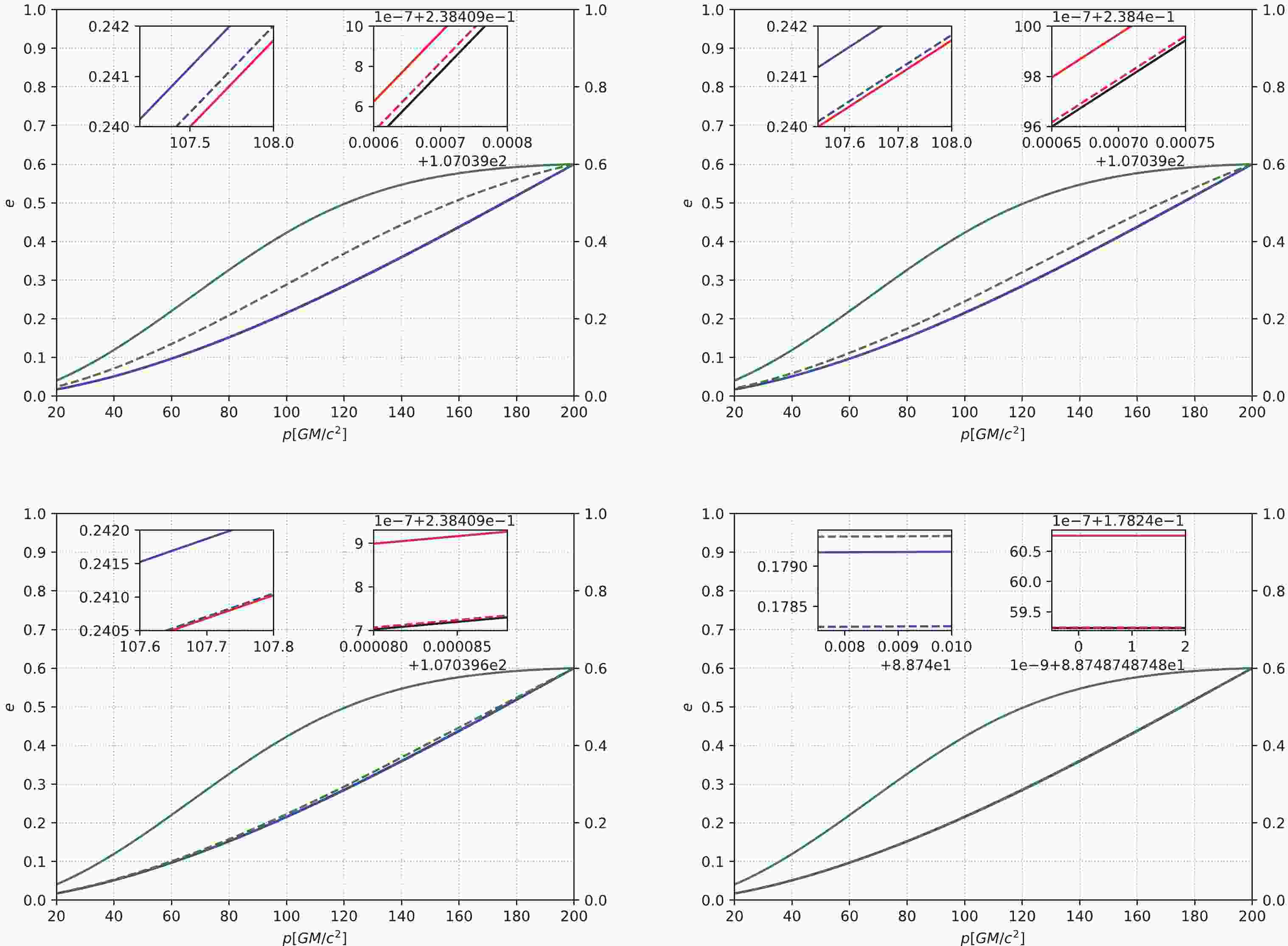
(24) Figures 1, 2, and 3 describe the p-e relation under different initial conditions, different profiles of DM spikes, and different masses of the center IMBH. When the initial p is relatively small, as shown in Fig. 1, for masses of different IMBHs, the curves of
$ \alpha = 1.5 $ and$ 2.0 $ are essentially the same as in the cases without DM, because for the case of$ \alpha = 1.5 $ and$ 2.0 $ , the proportion of DM is small compared to that of the center IMBH, so the contribution of DM to the eccentricity enhancement effect is almost negligible. This makes the curves of$ \alpha = 1.5 $ ,$ 2.0 $ , and the cases without DM basically overlap. For$ \alpha = 7/3 $ , the relatively denser DM spike can still decrease the orbit circularization rate of an IMRI. As the mass of the center IMBH increases, the curves for$ \alpha = 7/3 $ gradually tend toward those of cases without DM. In other words, for the case of$ \alpha = 7/3 $ , when the DM parameters are fixed, the mass of DM near a BH is certain. As the mass of the center IMBH increases, the relative proportion of DM decreases. The gravitational effect of the system (BH-DM) is gradually dominated by the BH, and the role of DM is negligible at this time. Therefore, as the mass of the center IMBH continues to increase, the eccentricity enhancement effect is almost the same as that of the cases without DM. When the initial p is relatively large, as shown in Figs. 2 and 3, for$ \alpha = 1.5 $ ,$ 2.0 $ , and$ 7/3 $ , the DM spike can significantly increase the eccentricity. In some cases, the eccentricity can even be close to$ 1 $ . When the eccentricity is close to$ 1 $ , a part of the three curves for$ \alpha = 1.5 $ ,$ 2.0 $ , and$ 7/3 $ overlaps, as shown in Fig. 3. As the mass of the IMBH increases, the three curves gradually tend toward those of the cases without DM.
Figure 1. (color online) The eccentricity e of an IMRI evolves with the semi-latus rectum p under different masses of the central IMBH. The horizontal axis is the semi-latus rectum p with units of
$ GM/c^{2} $ , and the vertical axis is the eccentricity e. In this figure, the solid lines represent IMBH masses of$ 10^{3} M_{\odot} $ , and the dashed lines from left to right represent IMBH masses of$ 1.5\times10^{3} M_{\odot} $ ,$ 2\times10^{3} M_{\odot} $ ,$ 3\times10^{3} M_{\odot} $ , and$ 5\times10^{3} M_{\odot} $ , respectively. We take the small compact object's mass as$ 10 M_{\odot} $ and the initial p as$ 200 GM/c^{2} $ . The black lines correspond to the absence of DM, and the red, blue, and green lines correspond to$ \alpha = 1.5 $ ,$ 2.0 $ , and$ 7/3 $ , respectively.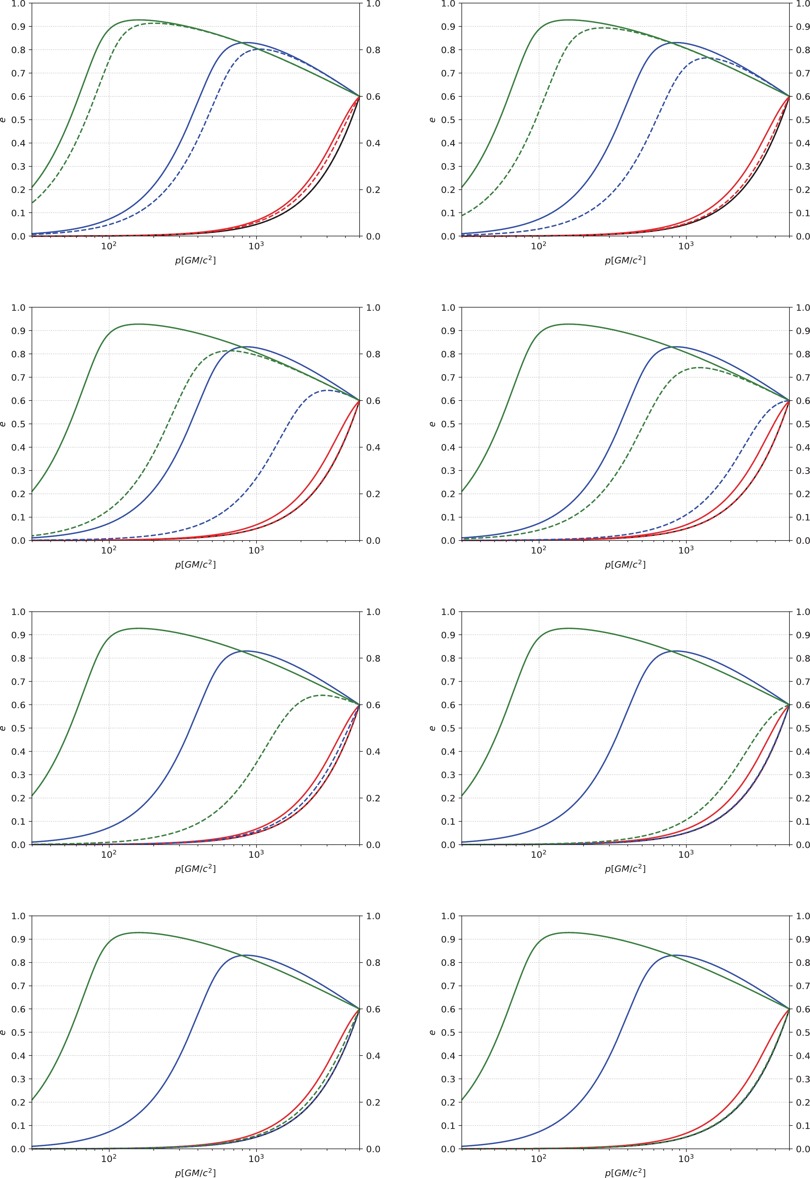
Figure 2. (color online) The eccentricity e of an IMRI evolves with the semi-latus rectum p under different masses of the central IMBH. The horizontal axis is the semi-latus rectum p with units of
$ GM/c^{2} $ , and the vertical axis is the eccentricity e. In this figure, the solid lines represent IMBH masses of$ 10^{3} M_{\odot} $ , and the dashed lines from left to right represent IMBH masses of$ 1.2\times10^{3} M_{\odot} $ ,$ 1.5\times10^{3} M_{\odot} $ ,$ 3\times10^{3} M_{\odot} $ ,$ 5\times10^{3} M_{\odot} $ ,$ 1\times10^{4} M_{\odot} $ ,$ 2\times10^{4} M_{\odot} $ ,$ 4\times10^{4} M_{\odot} $ , and$ 7\times10^{4} M_{\odot} $ , respectively. We take the small compact object's mass as$ 10 M_{\odot} $ and the initial p as$ 5000 GM/c^{2} $ . The black lines correspond to the absence of DM, and the red, blue, and green lines correspond to$ \alpha = 1.5 $ ,$ 2.0 $ , and$ 7/3 $ , respectively.
Figure 3. (color online) The eccentricity e of an IMRI evolves with the semi-latus rectum p under different masses of the central IMBH. The horizontal axis is the semi-latus rectum p with units of
$ GM/c^{2} $ , and the vertical axis is the eccentricity e. In this figure, the solid lines represent IMBH masses of$ 10^{3} M_{\odot} $ , and the dashed lines from left to right represent IMBH masses of$ 1.5\times10^{3} M_{\odot} $ ,$ 8\times10^{3} M_{\odot} $ ,$ 2\times10^{4} M_{\odot} $ ,$ 5\times10^{4} M_{\odot} $ ,$ 1\times10^{5} M_{\odot} $ ,$ 2\times10^{5} M_{\odot} $ ,$ 5\times10^{5} M_{\odot} $ , and$ 1\times10^{6} M_{\odot} $ , respectively. We take the small compact object's mass as$ 10 M_{\odot} $ and the initial p as$ 10^{5} GM/c^{2} $ . The black lines correspond to the absence of DM, and the red, blue, and green lines correspond to$ \alpha = 1.5 $ ,$ 2.0 $ , and$ 7/3 $ , respectively.Figures 4 and 5 depict the evolution of semi-latus rectum p and eccentricity e under different initial p and different IMBH masses. When the initial p is relatively small, as shown in the left panels, only the denser DM spike with
$ \alpha = 7/3 $ has a significant effect on the evolution, and it is the same under different IMBH masses. When the mass of an IMBH increases slightly, the evolution will accelerate. When the initial p is relatively larger, as shown in the right panels, the moderate DM spike can also accelerate the evolution, even under different IMBH masses. When the mass of the IMBH increases slightly, the evolution is delayed.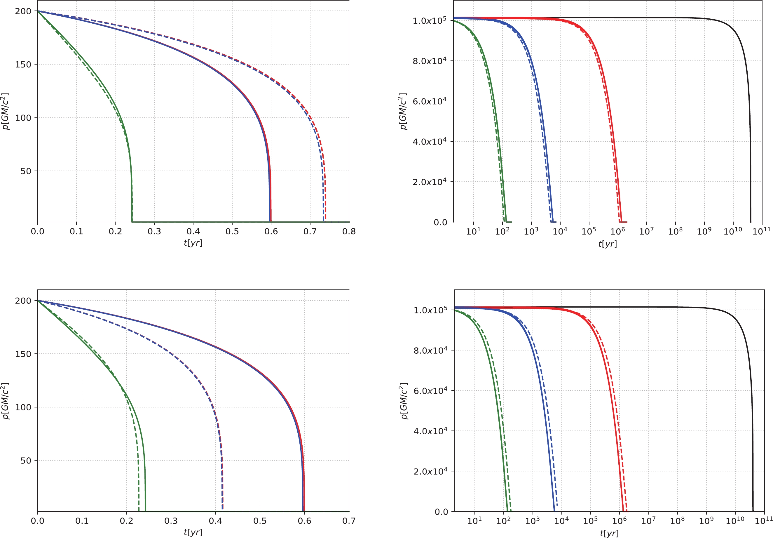
Figure 4. (color online) The semi-latus rectum p of an IMRI evolves with time t under different masses of IMBHs. The horizontal axis represents time t with the unit of year (yr), and the vertical axis represents the semi-latus rectum p with the unit of
$ GM/c^{2} $ . We take the small compact object's mass as$ 10 M_{\odot} $ , and the initial eccentricity$ e = 0.6 $ . The solid lines represent IMBH masses of$ 10^{3} M_{\odot} $ . The dashed lines represent IMBH masses of$ 9\times10^{2} M_{\odot} $ for the upper panels and$ 1.2\times10^{3} M_{\odot} $ for the lower panels. In the left panels, the initial p is set to$ 200 GM/c^{2} $ . In the right panels, the relatively large initial p is$ p\simeq10^{5} GM/c^{2} $ . The black lines correspond to the absence of DM, and the red, blue, and green lines correspond to$ \alpha = 1.5 $ ,$ 2.0 $ , and$ 7/3 $ , respectively.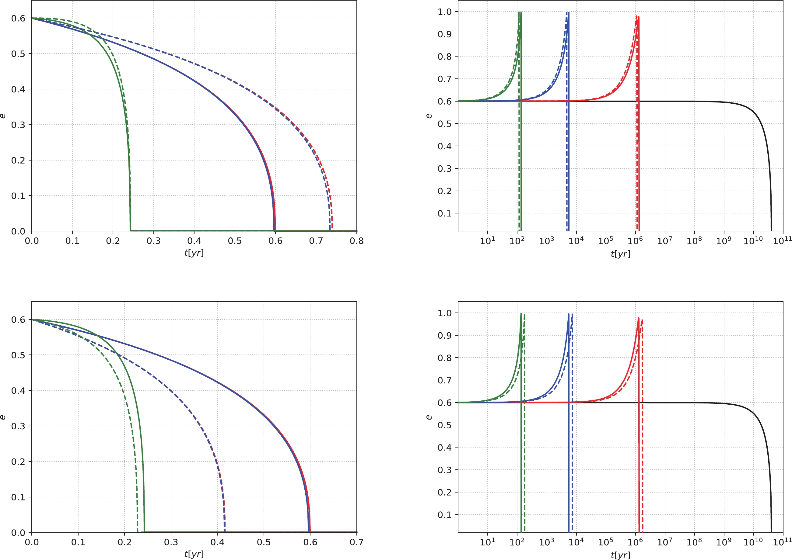
Figure 5. (color online) The eccentricity e of an IMRI evolves with time t under different masses of IMBHs. The horizontal axis represents time t with the unit of year (yr), and the vertical axis represents the eccentricity e. We take the small compact object's mass as
$ 10 M_{\odot} $ , and the initial eccentricity$ e = 0.6 $ . The solid lines represent IMBH masses of$ 10^{3} M_{\odot} $ . The dashed lines represent IMBH masses of$ 9\times10^{2} M_{\odot} $ for the upper panels and$ 1.2\times10^{3} M_{\odot} $ for the lower panels. In the left panels, the initial p is set to$ 200 GM/c^{2} $ . In the right panels, the relatively large initial p is$ p\simeq10^{5} GM/c^{2} $ . The black lines correspond to the absence of DM, and the red, blue, and green lines correspond to$ \alpha = 1.5 $ ,$ 2.0 $ , and$ 7/3 $ , respectively. -
(1) NFW density profile
According to the derivation process in subsection IIIA, for the NFW density profile, we can obtain the dynamical equations
$ \dot{p} = -\dfrac{64}{5}\dfrac{G^{3}\mu M^{2}}{c^{5}p^{3}}(1-e^{2})^{\frac{3}{2}}\left(1+\dfrac{7}{8}e^{2}\right)-\dfrac{4G^{\frac{1}{2}}\mu\rho_{\rm{0}}R_{\rm{s}}^{3}p^{\frac{3}{2}} \ln\Lambda}{M^{\frac{3}{2}}}(1-e^{2})^{\frac{3}{2}}\int_{0}^{2\pi}\dfrac{ (1+e\cos\phi)}{(1+2e\cos\phi+e^{2})^{\frac{3}{2}}[R_{\rm{s}}(1+e\cos\phi)+p]^{2}}{\rm d}\phi , $

(25) $ \dot{e} = -\dfrac{304}{15}\dfrac{G^{3}\mu M^{2}}{c^{5}p^{4}}(1-e^{2})^{\frac{3}{2}}e\left(1+\dfrac{121}{304}e^{2}\right)-\dfrac{4G^{\frac{1}{2}}\mu\rho_{\rm{0}}R_{\rm{s}}^{3}p^{\frac{1}{2}}\ln\Lambda}{M^{\frac{3}{2}}}(1-e^{2})^{\frac{3}{2}}\int_{0}^{2\pi}\dfrac{(e+\cos\phi)(1+e\cos\phi)}{(1+2e\cos\phi+e^{2})^{\frac{3}{2}}[R_{\rm{s}}(1+e\cos\phi)+p]^{2}}{\rm d}\phi . $

(26) The semi-major axis a and the semi-latus rectum p satisfy the equation
$ a = p/(1-e^{2}) $ . According to equations (25) and (26), using a instead of p to describe the dynamical equations yields$ \dot{e} = -\dfrac{304}{15}\dfrac{G^{3}\mu M^{2}}{c^{5}a^{4}}(1-e^{2})^{-\frac{5}{2}}e\left(1+\dfrac{121}{304}e^{2}\right)-\dfrac{4G^{\frac{1}{2}}\mu\rho_{\rm{0}}R_{\rm{s}}^{3}a^{\frac{1}{2}}\ln\Lambda}{M^{\frac{3}{2}}}(1-e^{2})^{2}\int_{0}^{2\pi}\dfrac{(e+\cos\phi)(1+e\cos\phi)}{(1+2e\cos\phi+e^{2})^{\frac{3}{2}}[R_{\rm{s}}(1+e\cos\phi)+a(1-e^{2})]^{2}}{\rm d}\phi , $

(27) $ \dot{a} = -\dfrac{64}{5}\dfrac{G^{3}\mu M^{2}}{c^{5}a^{3}}(1-e^{2})^{-\frac{7}{2}}\left(1+\dfrac{73}{24}e^{2}+\dfrac{37}{96}e^{4}\right)-\dfrac{4G^{\frac{1}{2}}\mu\rho_{\rm{0}}R_{\rm{s}}^{3}a^{\frac{3}{2}} \ln\Lambda}{M^{\frac{3}{2}}}(1-e^{2})\!\!\int_{0}^{2\pi}\!\!\dfrac{ (1+e\cos\phi)}{(1+2e\cos\phi+e^{2})^{\frac{1}{2}}[R_{\rm{s}}(1+e\cos\phi)+a(1-e^{2})]^{2}}{\rm d}\phi . $

(28) (2) TF density profile
According to the derivation process in subsection IIIA, for the TF density profile, we can get the dynamical equations
$ \dot{p} = -\dfrac{64}{5}\dfrac{G^{3}\mu M^{2}}{c^{5}p^{3}}(1-e^{2})^{\frac{3}{2}}\left(1+\dfrac{7}{8}e^{2}\right)-\dfrac{4G^{\frac{1}{2}}\mu\rho_{\rm{0}}p^{\frac{3}{2}} \ln\Lambda}{kM^{\frac{3}{2}}}(1-e^{2})^{\frac{3}{2}}\int_{0}^{2\pi}\dfrac{\sin\left(\dfrac{kp}{1+e\cos\phi}\right)}{(1+2e\cos\phi+e^{2})^{\frac{3}{2}}(1+e\cos\phi)}{\rm d}\phi , $

(29) $ \dot{e} = -\dfrac{304}{15}\dfrac{G^{3}\mu M^{2}}{c^{5}p^{4}}(1-e^{2})^{\frac{3}{2}}e\left(1+\dfrac{121}{304}e^{2}\right)-\dfrac{4G^{\frac{1}{2}}\mu\rho_{\rm{0}}p^{\frac{1}{2}}\ln\Lambda}{kM^{\frac{3}{2}}}(1-e^{2})^{\frac{3}{2}}\int_{0}^{2\pi}\dfrac{(e+\cos\phi)\sin\left(\dfrac{kp}{1+e\cos\phi}\right)}{(1+2e\cos\phi+e^{2})^{\frac{3}{2}}(1+e\cos\phi)}{\rm d}\phi . $

(30) The semi-major axis a and the semi-latus rectum p satisfy the equation
$ a = p/(1-e^{2}) $ . According to equations (29) and (30), using a instead of p to describe the dynamical equations yields$ \dot{e} = -\dfrac{304}{15}\dfrac{G^{3}\mu M^{2}}{c^{5}a^{4}}(1-e^{2})^{-\frac{5}{2}}e\left(1+\dfrac{121}{304}e^{2}\right)-\dfrac{4G^{\frac{1}{2}}\mu\rho_{\rm{0}}a^{\frac{1}{2}}\ln\Lambda}{kM^{\frac{3}{2}}}(1-e^{2})^{2}\int_{0}^{2\pi}\dfrac{(e+\cos\phi)\sin\left[\dfrac{ka(1-e^{2})}{1+e\cos\phi}\right]}{(1+2e\cos\phi+e^{2})^{\frac{3}{2}}(1+e\cos\phi)}{\rm d}\phi , $

(31) $ \dot{a} = -\dfrac{64}{5}\dfrac{G^{3}\mu M^{2}}{c^{5}a^{3}}(1-e^{2})^{-\frac{7}{2}}\left(1+\dfrac{73}{24}e^{2}+\dfrac{37}{96}e^{4}\right)-\dfrac{4G^{\frac{1}{2}}\mu\rho_{\rm{0}}a^{\frac{3}{2}} \ln\Lambda}{kM^{\frac{3}{2}}}(1-e^{2})\int_{0}^{2\pi}\dfrac{\sin\left[\dfrac{ka(1-e^{2})}{1+e\cos\phi}\right]}{(1+2e\cos\phi+e^{2})^{\frac{1}{2}}(1+e\cos\phi)}{\rm d}\phi . $

(32) (3) PI density profile
According to the derivation process in subsection IIIA, for the PI density profile, we obtain the dynamical equations
$\begin{aligned}[b] \dot{p} = -\dfrac{64}{5}\dfrac{G^{3}\mu M^{2}}{c^{5}p^{3}}(1-e^{2})^{\frac{3}{2}}\left(1+\dfrac{7}{8}e^{2}\right)-\dfrac{4G^{\frac{1}{2}}\mu\rho_{\rm{0}}R_{\rm{c}}^{2}p^{\frac{5}{2}} \ln\Lambda}{M^{\frac{3}{2}}}(1-e^{2})^{\frac{3}{2}}\int_{0}^{2\pi}\dfrac{1}{(1+2e\cos\phi+e^{2})^{\frac{3}{2}}[R_{\rm{c}}^{2}(1+e\cos\phi)^{2}+p^{2}]}{\rm d}\phi , \end{aligned} $

(33) $ \dot{e} = -\dfrac{304}{15}\dfrac{G^{3}\mu M^{2}}{c^{5}p^{4}}(1-e^{2})^{\frac{3}{2}}e\left(1+\dfrac{121}{304}e^{2}\right)-\dfrac{4G^{\frac{1}{2}}\mu\rho_{\rm{0}}R_{\rm{c}}^{2}p^{\frac{3}{2}}\ln\Lambda}{M^{\frac{3}{2}}}(1-e^{2})^{\frac{3}{2}}\int_{0}^{2\pi}\dfrac{(e+\cos\phi)}{(1+2e\cos\phi+e^{2})^{\frac{3}{2}}[R_{\rm{c}}^{2}(1+e\cos\phi)^{2}+p^{2}]}{\rm d}\phi . $

(34) The semi-major axis a and the semi-latus rectum p satisfy the equation
$ a = p/(1-e^{2}) $ . According to equations (33) and (34), using a instead of p to describe the dynamical equations yields$ \begin{aligned}[b] \dot{e} = & -\dfrac{304}{15}\dfrac{G^{3}\mu M^{2}}{c^{5}a^{4}}(1-e^{2})^{-\frac{5}{2}}e\left(1+\dfrac{121}{304}e^{2}\right) \\& -\dfrac{4G^{\frac{1}{2}}\mu\rho_{\rm{0}}R_{\rm{c}}^{2}a^{\frac{3}{2}}\ln\Lambda}{M^{\frac{3}{2}}}(1-e^{2})^{3}\int_{0}^{2\pi}\dfrac{(e+\cos\phi)}{(1+2e\cos\phi+e^{2})^{\frac{3}{2}}[R_{\rm{c}}^{2}(1+e\cos\phi)^{2}+a^{2}(1-e^{2})^{2}]}{\rm d}\phi , \end{aligned}$

(35) $\begin{aligned}[b] \dot{a}=&-\dfrac{64}{5}\dfrac{G^{3}\mu M^{2}}{c^{5}a^{3}}(1-e^{2})^{-\frac{7}{2}}\left(1+\dfrac{73}{24}e^{2}+\dfrac{37}{96}e^{4}\right) \\& -\dfrac{4G^{\frac{1}{2}}\mu\rho_{\rm{0}}R_{\rm{c}}^{2}a^{\frac{5}{2}} \ln\Lambda}{M^{\frac{3}{2}}}(1-e^{2})^{2}\int_{0}^{2\pi}\dfrac{1}{(1+2e\cos \phi+e^{2})^{\frac{1}{2}}[R_{\rm{c}}^{2}(1+e\cos\phi)^{2}+a^{2}(1-e^{2})^{2}]}{\rm d}\phi . \label{a_t_PI} \end{aligned}$

(36) Figure 6 depicts the relation between p and e under different initial conditions and different DM profiles. When the initial p is relatively small (
$ p = 10^{4} GM/c^{2} $ ), as shown in the left panels, the three curves without DM spikes (including the NFW density profile, the PI density profile, and the TF density profile) and the curves without DM are essentially indistinguishable. However, the DM spikes with$ \alpha = 1.5 $ ,$ 2.0 $ , and$ 7/3 $ can increase the eccentricity, and the larger the value of$ \alpha $ , the faster the increase in eccentricity. For$ \alpha = 2.0 $ and$ 7/3 $ , the eccentricity can even be close to$ 1 $ . When the initial p is relatively large ($ p\simeq10^{5} GM/c^{2} $ ), as shown in the right panels, for the cases without DM spikes, the curves of PI and TF density profiles overlap completely, and the curves without DM are also completely consistent with them; the NFW density profile can increase the eccentricity significantly. For the case of DM spikes, for$ \alpha = 1.5 $ ,$ 2.0 $ , and$ 7/3 $ , the eccentricity increases obviously, even approaching$ 1 $ . When the eccentricity is near$ 1 $ , a portion of the curves for$ \alpha = 2.0 $ and$ 7/3 $ overlaps.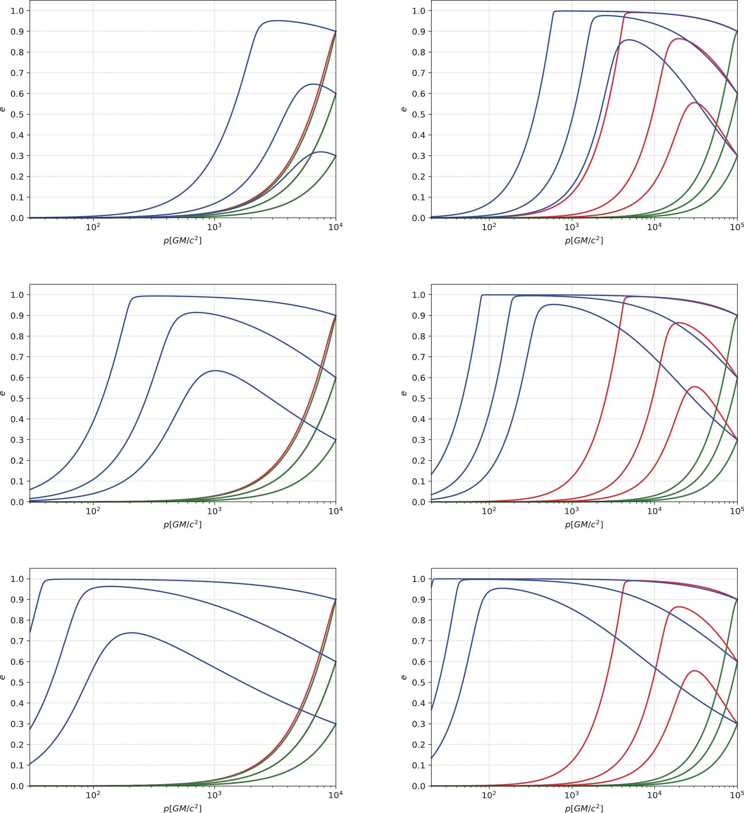
Figure 6. (color online) The eccentricity e of an IMRI evolves with the semi-latus rectum p under different density profiles of DM. The horizontal axis represents the semi-latus rectum p with the unit of
$ GM/c^{2} $ , and the vertical axis represents the eccentricity e. In this figure, we take the small compact object's mass as$ 10 M_{\odot} $ and the IMBH's mass as$ 10^{3} M_{\odot} $ . The blue lines correspond to the existence of DM spikes. The black lines correspond to the case without DM. The other lines correspond to the cases without DM spikes (i.e., the red, green, and yellow lines correspond to the NFW density profile, the PI density profile, and the TF density profile, respectively. Here, the green, yellow, and black lines overlap). In the left panels, the initial p is set to$ 10^{4} GM/c^{2} $ . In the right panels, the relatively large initial p is$ p\simeq10^{5} GM/c^{2} $ . These panels correspond to$ \alpha = 1.5 $ ,$ 2.0 $ , and$ 7/3 $ from top to bottom.Figure 7 describes the evolution of p and e under different initial conditions and different DM profiles. When the initial p is relatively small (
$ p = 200 GM/c^{2} $ ), as shown in the upper panels, the DM profiles without spikes (including the NFW density profile, the PI density profile, and the TF density profile) and the case without DM are essentially indistinguishable from the profile of DM spikes with$ \alpha = 1.5 $ and$ 2.0 $ in terms of their impact on evolution. Only the denser DM spike with$ \alpha = 7/3 $ influences the evolution significantly. When the initial p is relatively large ($ p\simeq10^{5} GM/c^{2} $ ), as shown in the lower panels, regardless of whether there is a DM spike, the evolution will be accelerated. However, the presence of a DM spike has a greater impact on the evolution, and when$ \alpha $ is larger, the evolution will be faster.
Figure 7. (color online) The semi-latus rectum p and the eccentricity e of an IMRI evolve with time t under different initial p. The horizontal axis represents time t with the unit of year (yr), and the vertical axis represents the semi-latus rectum p with the unit of
$ GM/c^{2} $ for the upper panels and the eccentricity e for the lower panels. In this figure, we take the small compact object's mass as$ 10 M_{\odot} $ , the IMBH's mass as$ 10^{3} M_{\odot} $ , and the initial eccentricity$ e = 0.6 $ . The blue lines correspond to the existence of DM spikes. The black lines correspond to the case without DM. The other lines correspond to the cases without DM spikes (i.e., the red, green, and yellow lines correspond to the NFW density profile, the PI density profile, and the TF density profile, respectively; here, the green, yellow, and black lines overlap). The solid, dashed, and dotted blue lines correspond to$ \alpha = 1.5 $ ,$ 2.0 $ , and$ 7/3 $ , respectively. In the upper panels, the initial p is set to$ 200 GM/c^{2} $ . In the lower panels, the relatively large initial p is$ p\simeq10^{5} GM/c^{2} $ . -
In this work, we have considered the effect of DM and IMBH mass on the eccentricity of an IMRI system. Specifically, we have considered the influence of a DM spike on the eccentricity under the same mass of the center IMBH, the change of different IMBH masses with respect to the eccentricity when a DM spike exists, and a change of the DM halo with respect to the eccentricity under the absence of a DM spike. We found the following:
$ (1) $ the mass of the center IMBH can be measured by observing the change in orbital eccentricity of the stellar massive BH at different scales, and the measurable mass will adhere to a certain range;$ (2) $ by measuring the orbital eccentricity of the stellar massive BH for an IMRI, it is possible to study the DM model at the scale of$ 10^{5} GM/c^{2} $ .When a DM spike is present, the eccentricity is increased. For a denser DM spike with
$ \alpha = 7/3 $ and a larger initial p, the eccentricity will increase obviously, which is consistent with the results of [1]. This indicates that the result is no different from the power-law distribution by using a more accurate profile of the DM spike. In the presence of a DM spike, we found that by adjusting the mass of the IMBH, the orbital eccentricity of the stellar massive BH changes accordingly. Specifically, when the mass of the center IMBH increases, the enhancement effect of the eccentricity decreases significantly; when the IMBH's mass decreases, the enhancement effect of the eccentricity increases obviously. This suggests that by observing the eccentricity of a stellar massive BH, it is possible to estimate the mass of the center BH. Clearly, measuring the eccentricity at different scales will cause differences in the center BH's mass that can be detected.Next, we obtained the magnitude of the eccentricity enhancement of the stellar BH in the presence and absence of a DM spike. We found that when there is a DM spike near the IMBH, the eccentricity has a significant enhancement effect at the scale of
$ 20 GM/c^{2}\sim 10^{5} GM/c^{2} $ ; however, when there is no DM spike and only the DM halo is considered, the eccentricity increases obviously at the scale of approximately$ 10^{5} GM/c^{2} $ , and the increase is much smaller than that in the case with a DM spike. This shows that by measuring the eccentricity of the stellar BH at the scale of$ 10^{5} GM/c^{2} $ , it is possible to investigate the distribution of DM in the vicinity of the center BH, so as to study the DM model more deeply.In future work, we will calculate the enhancement effect of different BH models and their properties on the eccentricity for an IMRI, so as to study the BH model intensively.
-
We thank the anonymous reviewer for a constructive report that has significantly improved this paper.
The eccentricity enhancement effect of intermediate-mass-ratio-inspirals: dark matter and black hole mass
- Received Date: 2020-08-04
- Available Online: 2021-01-15
Abstract: It was found that dark matter (DM) in an intermediate-mass-ratio-inspiral (IMRI) system has a significant enhancement effect on the orbital eccentricity of a stellar massive compact object, such as a black hole (BH), which may be tested by space-based gravitational wave (GW) detectors, including LISA, Taiji, and Tianqin in future observations. In this paper, we study the enhancement effect of the eccentricity for an IMRI under different DM density profiles and center BH masses. Our results are as follows: (1) in terms of the general DM spike distribution, the enhancement of the eccentricity is basically consistent with the power-law profile, which indicates that it is reasonable to adopt the power-law profile; (2) in the presence of a DM spike, the different masses of the center BH will affect the eccentricity, which provides a new way for us to detect the BH's mass; and (3) considering the change in the eccentricity in the presence and absence of a DM spike, we find that it is possible to distinguish DM models by measuring the eccentricity at a scale of approximately


 DownLoad: